- Terminal Board Signal Wiring and Frame Grabber System Architecture Overview
- Wiring External Input Signals to the Terminal Board
- Wiring Strob Output from the Terminal Board
- Trigger Camera Control Method
Terminal Board Signal Wiring and Frame Grabber System Architecture Overview
This section will explain how to connect the Terminal Board to the Coaxlink’s I/O board and verify signal reception.
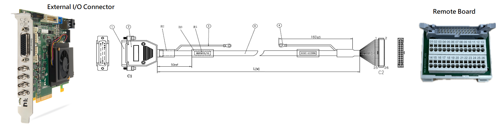
CXP Series & Grablink Duo I/O Connector (Pin Define) | Terminal Board (Pin Define)|Terminal Board Datasheet
You can find more information in the official Euresys documentation.
CXP Series & Grablink Duo I/O Connector
| Pin | Signal | Usage |
|---|---|---|
| 1 | GND | Ground |
| 2 | DIN12+ | High-speed differential input #12 – Positive pole |
| 3 | IIN11+ | Isolated input #11 – Positive pole |
| 4 | IIN13- | Isolated input #13 – Negative pole |
| 5 | IIN14- | Isolated input #14 – Negative pole |
| 6 | IOUT12- | Isolated contact output #12 – Negative pole |
| 7 | GND | Ground |
| 8 | Not connected | |
| 9 | GND | Ground |
| 10 | GND | Ground |
| 11 | DIN12- | High-speed differential input #12 – Negative pole |
| 12 | IIN11- | Isolated input #11 – Negative pole |
| 13 | IIN12+ | Isolated input #12 – Positive pole |
| 14 | IIN13+ | Isolated input #13 – Positive pole |
| 15 | IIN14+ | Isolated input #14 – Positive pole |
| 16 | IOUT12+ | Isolated contact output #12 – Positive pole |
| 17 | TTLIO12 | TTL input/output #12 |
| 18 | GND | Ground |
| 19 | DIN11- | High-speed differential input #11 – Negative pole |
| 20 | DIN11+ | High-speed differential input #11 – Positive pole |
| 21 | IIN12- | Isolated input #12 – Negative pole |
| 22 | IOUT11- | Isolated contact output #11 – Negative pole |
| 23 | IOUT11+ | Isolated contact output #11 – Positive pole |
| 24 | GND | Ground |
| 25 | TTLIO11 | TTL input/output #11 |
| 26 | +12V | +12 V Power output |
Back to Wiring Map Back to Top
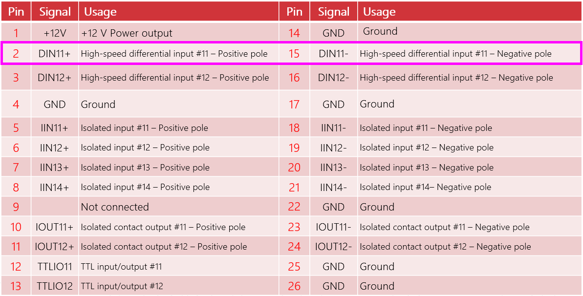
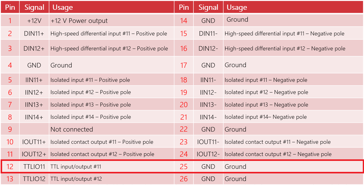
Terminal Board Pin Define ( CXP Series & Grablink Duo)
| Pin | Signal | Usage | Pin | Signal | Usage |
|---|---|---|---|---|---|
| 1 | +12V | +12 V Power output | 14 | GND | Ground |
| 2 | DIN11+ | High-speed differential input #11 – Positive pole | 15 | DIN11- | High-speed differential input #11 – Negative pole |
| 3 | DIN12+ | High-speed differential input #12 – Positive pole | 16 | DIN12- | High-speed differential input #12 – Negative pole |
| 4 | GND | Ground | 17 | GND | Ground |
| 5 | IIN11+ | Isolated input #11 – Positive pole | 18 | IIN11- | Isolated input #11 – Negative pole |
| 6 | IIN12+ | Isolated input #12 – Positive pole | 19 | IIN12- | Isolated input #12 – Negative pole |
| 7 | IIN13+ | Isolated input #13 – Positive pole | 20 | IIN13- | Isolated input #13 – Negative pole |
| 8 | IIN14+ | Isolated input #14 – Positive pole | 21 | IIN14- | Isolated input #14– Negative pole |
| 9 | Not connected | 22 | GND | Ground | |
| 10 | IOUT11+ | Isolated contact output #11 – Positive pole | 23 | IOUT11- | Isolated contact output #11 – Negative pole |
| 11 | IOUT12+ | Isolated contact output #12 – Positive pole | 24 | IOUT12- | Isolated contact output #12 – Negative pole |
| 12 | TTLIO11 | TTL input/output #11 | 25 | GND | Ground |
| 13 | TTLIO12 | TTL input/output #12 | 26 | GND | Ground |
Back to Wiring Map Back to Top
Wiring External Input Signals to the Terminal Board
In this case, as encoder signals are being used, the High-speed differential input #11 has been selected as the connection point for its capability to handle high-speed signals. For signals that are not high-speed, standard input ports can be utilized. It’s important to select an appropriate input port based on the signal speed to ensure optimal performance and accuracy of the system.
Wiring Strob Output from the Terminal Board
Trigger Camera Control Method
- NC Mode (Freerun): The camera captures images continuously at its own pace, independent of external signals.
- RC Mode (Rate Control): The frame grabber controls the camera cycle rate (it triggers each new cycle), while the exposure duration is set by the camera itself. Used with asynchronous-reset cameras.
- RG Mode (Asynchronous): The frame grabber dictates the camera's cycle rate and exposure, synchronizing it with external triggers like an encoder.
RG Mode is ideal for situations requiring precise timing control, such as high-speed imaging or synchronized event capture. Select the mode that best fits your application’s requirements.
Configuration in the Device Tab (Step 1)
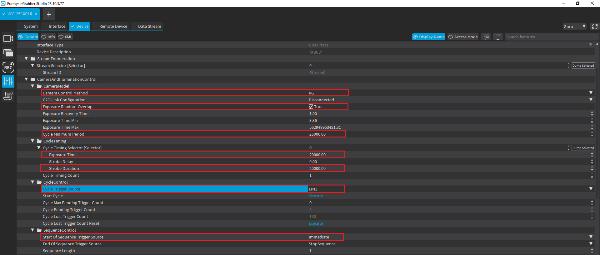
- Set the Camera Control Method to RG.
- Enable Exposure Readout Overlap to allow the exposure and readout processes to overlap, optimizing the camera cycle time.
- Set the Cycle Trigger Source to Immediate, which triggers the camera cycle without waiting for an external trigger.
- The Cycle Trigger Source is a critical setting. Choose LIN1 (see Step 3 for detailed settings) or Divider as the source. It's essential to set this parameter correctly for proper system operation.
Calculating the Cycle Minimum Period
- Cycle Minimum Period = 1 / 40 FPS = 0.025 seconds = 25 milliseconds (ms)
- Exposure Time = 20000 microseconds (20 ms), which is less than the 25 ms limit.
- Strobe Duration = 20000 microseconds (20 ms), which also does not exceed the 25 ms limit.
Setting the TriggerSource(Step 2)
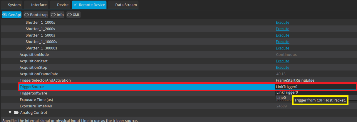
Different camera manufactures might use different names for their parameters.Always check with the camera manufacturer on parameters to set.
Setting the InputTool (Step 3)
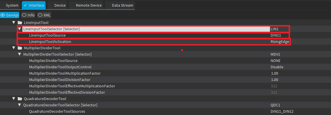
When configuring the InputTool in your system, it’s important to understand the function of each parameter:
- LineInputToolSelector: This parameter serves as a central reference for the InputTool configuration, encompassing the selected source and activation mode for the input. Once set, LineInputToolSelector ensures consistency across the system; any changes made to this parameter will automatically update all related settings that reference it. This feature streamlines the process of modifying the input source or trigger method, as adjustments need only be made once at this central point.
- LineInputToolSource: This parameter defines the source of the input signal. It can be used to specify where the signal is coming from, such as a specific hardware port or an internal source.
- LineInputToolActivation: This parameter sets the activation mode of the input tool. It determines how the tool reacts to the input signal, such as triggering on a rising edge, falling edge, or other condition.
Properly configuring these parameters ensures that your system accurately responds to external signals and triggers. Back to Top
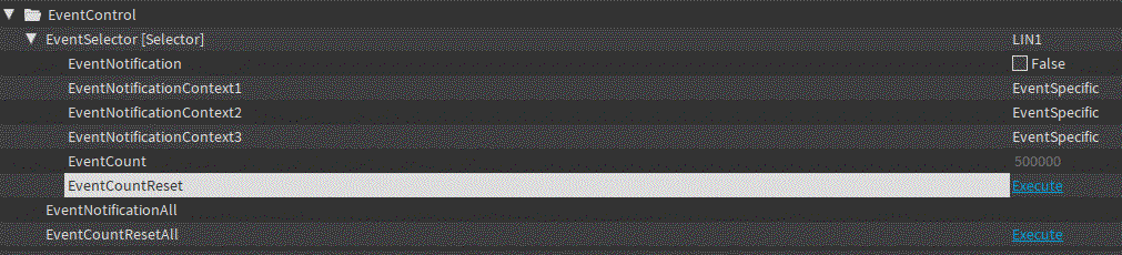
Verifying Operation with EventCount (Step 4)
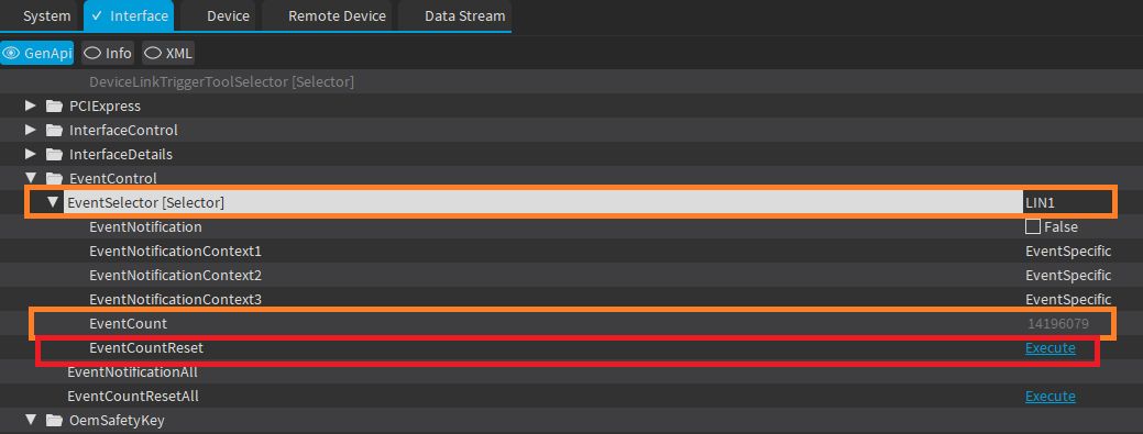
- EventSelector: This parameter allows you to select the source for event monitoring. You can set it to LIN1 (as described in Step 3) or choose Divider as the source. Selecting the correct EventSelector enables you to track specific events relevant to your input configuration.
- EventCount: This parameter displays the count of the events detected. A value in EventCount indicates successful operation. For consistent movements over fixed distances, you will observe an equivalent accumulation in the EventCount value.
- EventCountReset: This parameter can be used to reset the EventCount value. It is useful for clearing the count to facilitate easier tracking and calculations of new events.
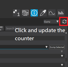
Click the button shown in the figure below to retrieve the current counter value.
Setting the Strobe Output (Step 5)
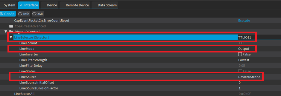
- LineSelector [Selector]: This parameter is set to TTLIO11 to select the corresponding line for strobe output configuration.
- LineMode: The line mode is set to Output, which configures the selected line to act as an output, driving the strobe signal.
- LineSource: The source for the line is set to Device0Strobe
Setting the Cycle Trigger Source(Step 6)
Most encoders emit high-frequency signals, which are often too rapid for direct camera triggering. Using a divider, these signals can be adjusted to lower frequencies, suitable for stable camera activation, ensuring accurate and consistent image capturing.
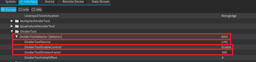
- DividerToolSelector: This parameter acts as the central identifier for the Divider Tool configuration, integrating the selected source (specified by DividerToolSource), the activation control (determined by DividerToolEnableControl), and the division factor (set by DividerToolDivisionfactor) for the input. Once DividerToolSelector is configured, it guarantees consistency across the system; any subsequent modifications to the source, activation, or division factor are centralized through this single parameter. This consolidation simplifies the adjustment process, enabling changes to be made in one place that then propagate to all related configurations.
- DividerToolSource: Select LIN1 for the source, as previously described in Step 3.
- DividerToolEnableControl: Set this to 'Enable' to activate the divider tool.
- DividerToolDivisionfactor: Enter the division factor value you wish to use for frequency division.
Once you have configured the Divider Tool, remember to revisit Step 1 to adjust the ‘Cycle Trigger Source’ accordingly. Additionally, you can verify the functionality by modifying the ‘EventSelector’ in Step 4. These steps ensure that your settings are consistent and functional across the system.