How to use NEON to control DI/O?
Here is the list for our demo devices. Different devices might have different default settings. Please adjust the procedures based on your corresponding devices.
Easy
Devices List:
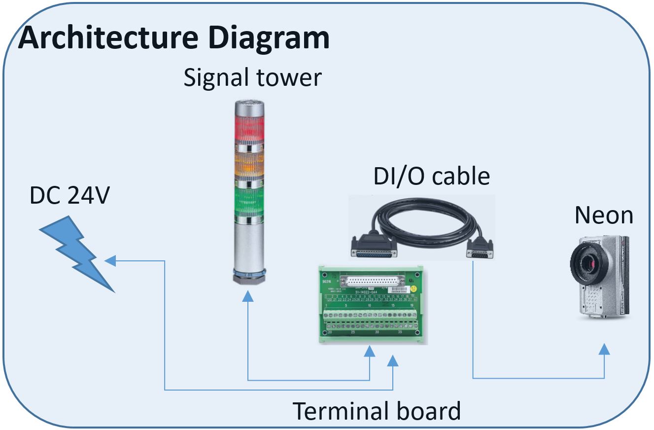
- NEON-2000-JNX Series Starter Kit
- ADLINK DIN-37D-01
- PATLITE MES-_02A
- 24V Power Supply
Architecture diagram
Overview
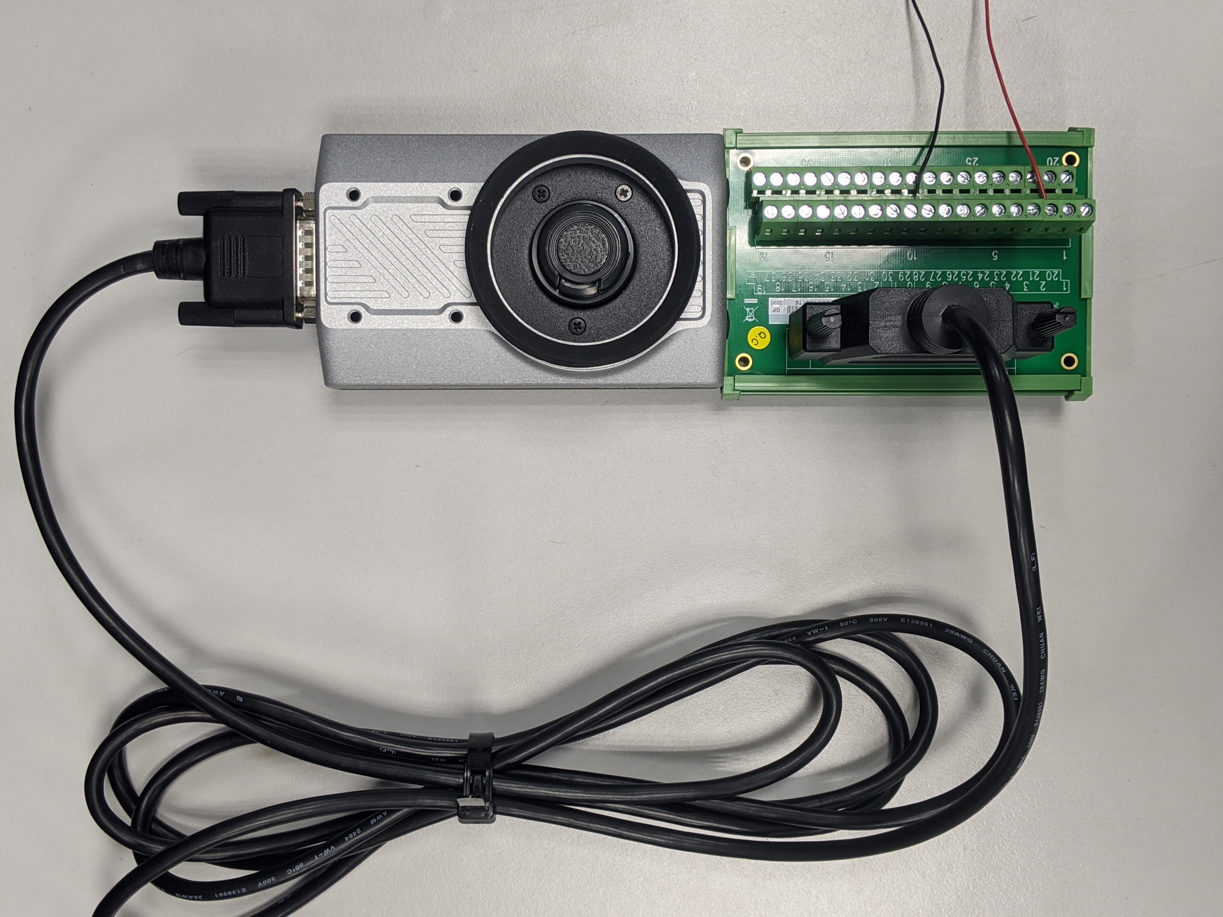
Wiring
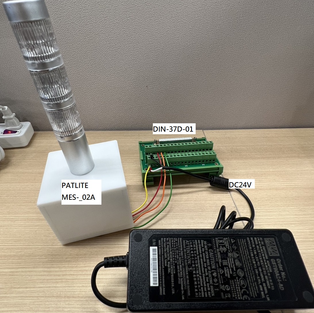
- Step 1. Connect the Neon with the din board through a connector.
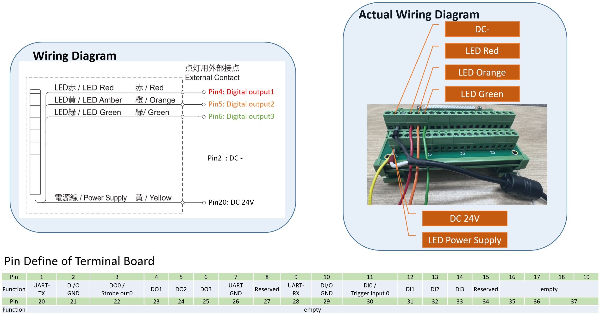
- Step 2. Connect the Red LED’s wire in pin 4 for digital output (we take DO1 as an example).
- Step 3. Plug the 24V power supply’s negative wire in Din board’s pin 2 for grounding.
- Step 4. Connect the positive of power supply with the positive of LED. It shorts the two wires at pin20 which is reserved as terminal.
- Step 5. Use Neon to control the LED.
- Use the command
cd /usr/src/Neon/Sample/Neon_Settingto adjust Neon setting. - Use
sudo ./NeonSet DO 1 1to turn on the LED, usesudo ./NeonSet DO 1 0to turn off the LED conversely.
Note
Due to dual function of DO0 and DI0, the default function of DO0 is strobe out and DI0 is trigger in. If you want to set them as general DO and DI. Please configure it as following:
- DIO0Config 1: Set DIO0 as GPDI and GPDO0
- DIO0Config 0: Set DIO0 as Trigger in and Strobe out (default)
Set DIO0 as GPDI and GPDO0
sudo /usr/src/Neon/Sample/Neon_Setting/NeonSet DIO0Config 1
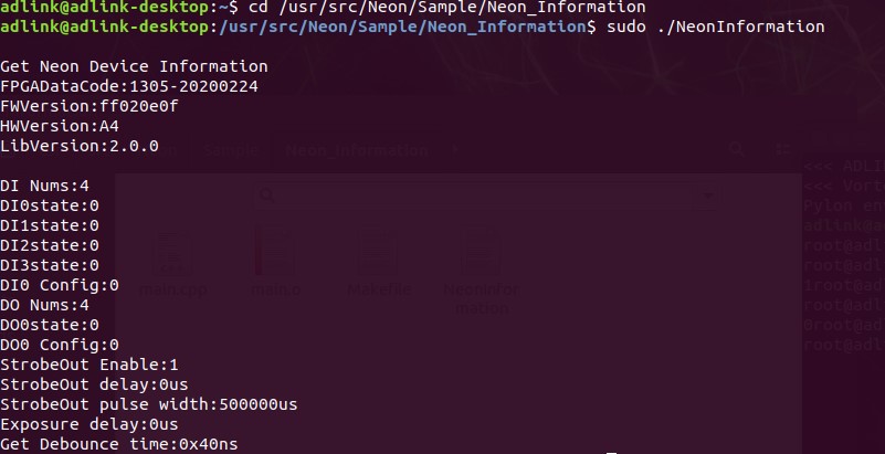
 Check the information of DIO.
sudo /usr/src/Neon/Sample/Neon_Information/NeonInformation
Intermediate
Devices List:
- ADLINK NEON-1000-MDX
- ADLINK DIN-37D-01
- High Bright Tech PC-24V24W-2-S
- 5V Power Supply
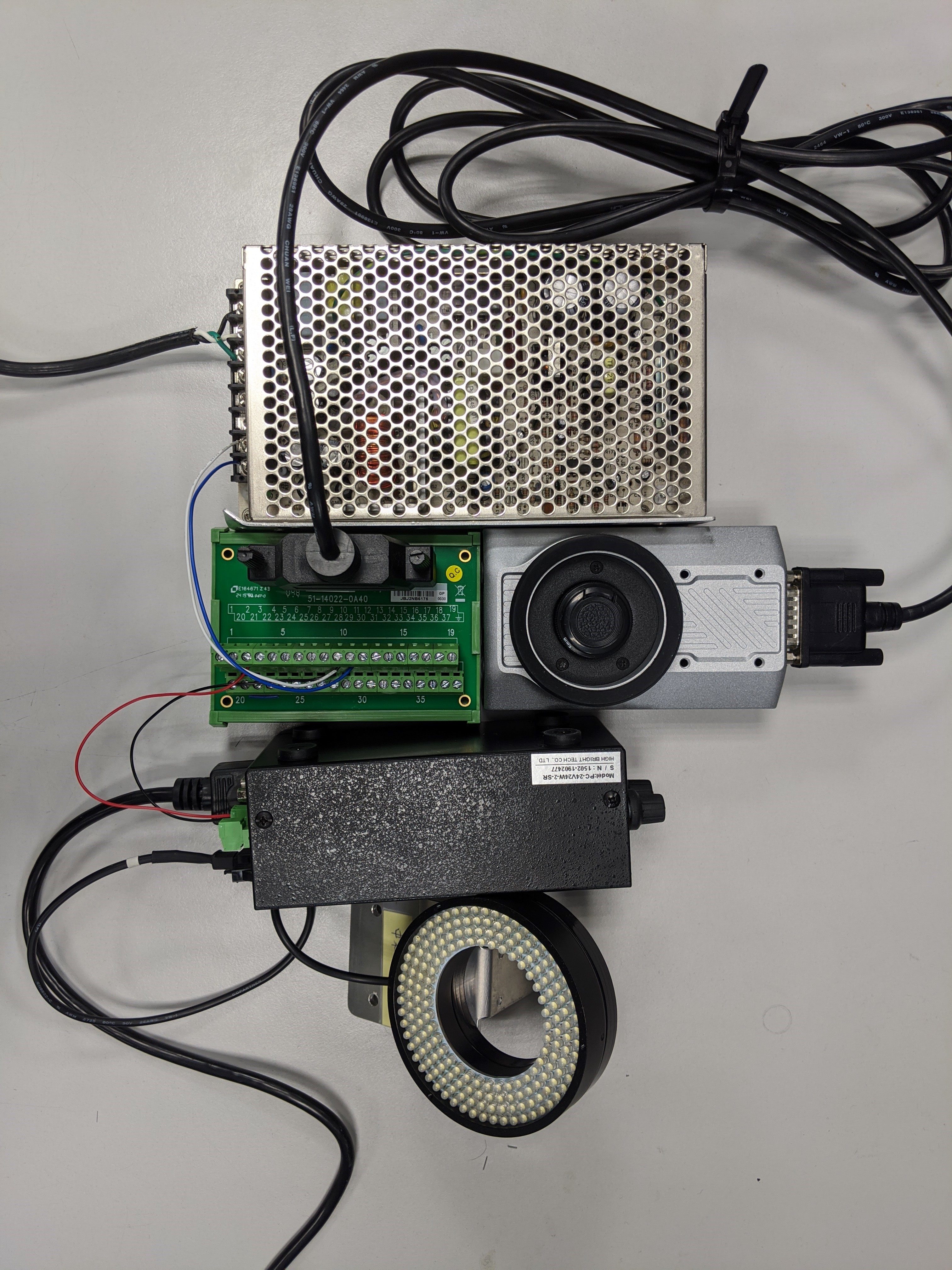
Step 1.
Connect the light with the light controller at channel 1.
Step 2.
Connect the light controller with din board at strobe channel 1. Plug the positive wire in pin 3 for device output, and plug the negative wire in the pin 10 for grounding.
Step 3.
Connect the Neon with the din board through a connector.
Step 4.
Connect a trigger device on the din board. Insert the positive wire at pin 11 for trigger in, insert the negative wire at pin 10 for grounding. Here we used a 5V power supply for demonstration, you could connect your own device for your own purposes.

Step 5.
Adjust the default settings from Neon. Please enter the specific file path to adjust the settings. We modified the strobe-out polarity to set turning off the light as default, this step might be different due to your controller devices. Once the Neon reboots, the setting would be restored.
- Use command
sudo -ito get in root mode.

- Use the command
cd /sys/class/neon_camctrlto change directory.

- Use
catcommand to check current status. To change the default setting of strobe-out polarity, use the commandecho 1 >StrobeOutPolarity.

Step 6.
To extend or narrow the device strobe out time, please follow the steps
- Use the command
cd /usr/src/Neon/Sample/Neon_Settingto change the current working directory.

- To adjust the strobe out time, use the command
sudo ./NeonSet StrobeOutPulseWidth N. The parameter N is the time of the width, the unit is us(10^-6 second).

- For checking current infos of Neon, please change the directory with the command
cd /usr/src/Neon/Sample/Neon_Information. Usesudo ./NeonInformationto get current status.